Showing posts with label ARDUINO PROJECTS. Show all posts

Easy and Simple An Arduino Based Fire Fighting Robot

   In this project, we will learn how to build a simple robot using Arduino that could move towards the fire and pump out water around it to put down the fire. It is a very simple robot that would teach us the underlying concept of robotics; 

   According to National Crime Records Bureau (NCRB), it is estimated that more than 1.2 lakh deaths have been caused because of fire accidents in India from 2010-2014. Even though there are a lot of precautions taken for Fire accidents, these natural/man-made disasters do occur now and then. In the event of a fire breakout, to rescue people and to put out the fire we are forced to use human resources which are not safe. With the advancement of technology especially in Robotics it is very much possible to replace humans with robots for fighting the fire. This would improve the efficiency of firefighters and would also prevent them from risking human lives. Today we are going to build a Fire Fighting Robot using Arduino, which will automatically sense the fire and start the water pump.

   you would be able to build more sophisticated robots once you understand the following basics. So let’s get started...


Material Required:

  1. Arduino UNO
  2. Fire sensor or Flame sensor (3 Nos)
  3. Servo Motor (SG90)
  4. L293D motor Driver module
  5. Small Breadboard
  6. Robot chassis with motors and wheel (any type)
  7. A small can
  8. Connecting wires 

Working Concept of Fire Fighting Robot:

The main brain of this project is the Arduino, but in-order to sense fire we use the Fire sensor module(flame sensor) that is shown below.

As you can see these sensors have an IR Receiver (Photodiode) which is used to detect the fire. How is this possible? When fire burns it emits a small amount of Infra-red light, this light will be received by the IR receiver on the sensor module. Then we use an Op-Amp to check for change in voltage across the IR Receiver, so that if a fire is detected the output  pin (DO) will give 0V(LOW) and if the is no fire the output pin will be 5V(HIGH).
So, we place three such sensors in three directions of the robot to sense on which direction the fire is burning.

We detect the direction of the fire we can use the motors to move near the fire by driving our motors through the L293D module. When near a fire we have to put it out using water. Using a small container we can carry water, a 5V pump is also placed in the container and the whole container is placed on top of a servo motor so that we can control the direction in which the water has to be sprayed. Let’s proceed with the connections now

Circuit Diagram:

The complete circuit diagram for this Fire Fighting Robot is given below

You can either connect all the shown connections for uploading the program to check the working or you can assemble the bot completely and then proceed with the connections. Both ways the connections are very simple and you should be able to get it right.
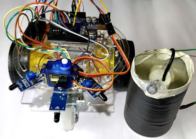
Based on the robotic chassis that you are using you might not be able to use the same type of container that I am using. In that case use your own creativity to set up the pumping system. However the code will remain same. I used a small aluminium can (cool drinks can) to set the pump inside it and poured water inside it. I then assembled the whole can on top of a servo motor to control the direction of water. My robot looks something like this after assembly.
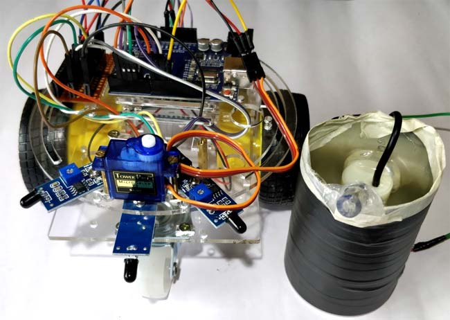


As you can see, I have fixed the servo fin to the bottom of the container using got glue and have fixed the servo motor with chassis using nuts and bolts.  We can simply place the container on top of the motor and trigger the pump inside it to pump water outside through the tube. The whole container can then be rotated using the servo to control the direction of the water.

Programming your Arduino:

Once you are ready with your hardware, you can upload the Arduino code for some action. The complete program is given at the end of this page. However I have further explained few important bits and pieces here.
 As we know the fire sensor will output a HIGH when there is fire and will output a LOW when there is fire. So we have to keep checking these sensor if any fire has occurred. If no fire is there we ask the motors to remain stop by making all the pins high as shown below
if (digitalRead(Left_S) ==1 && digitalRead(Right_S)==1 && digitalRead(Forward_S) ==1) //If Fire not detected all sensors are zero
    {
    //Do not move the robot
    digitalWrite(LM1, HIGH);
    digitalWrite(LM2, HIGH);
    digitalWrite(RM1, HIGH);
    digitalWrite(RM2, HIGH);
    }

 Similarly, if there is any fire we can ask the robot to move in that direction by rotating the respective motor. Once it reaches the fire the left and right sensor will not detect the fire as it would be standing straight ahead of the fire. Now we use the variable named “fire” that would execute the function to put off the fire.


 else if (digitalRead(Forward_S) ==0) //If Fire is straight ahead
    {
    //Move the robot forward
    digitalWrite(LM1, HIGH);
    digitalWrite(LM2, LOW);
    digitalWrite(RM1, HIGH);
    digitalWrite(RM2, LOW);
    fire = true;
    }

Once the variable fire becomes true, the fire fighting robot arduino code will execute the put_off_firefunction until the fire is put off. This is done using the code below.
     while (fire == true)
     {
      put_off_fire();
     }
   
Inside the put_off_fire() we just have to stop the robot by making all the pins high. Then turn on the pump to push water outside the container, while this is done we can also use the servo motor to rotate the container so that the water is split all over uniformly. This is done using the code below
void put_off_fire()
{
     delay (500);
    digitalWrite(LM1, HIGH);
    digitalWrite(LM2, HIGH);
    digitalWrite(RM1, HIGH);
    digitalWrite(RM2, HIGH);  
   digitalWrite(pump, HIGH); delay(500);
    for (pos = 50; pos <= 130; pos += 1) {
    myservo.write(pos);
    delay(10); 
  }
 for (pos = 130; pos >= 50; pos -= 1) {
    myservo.write(pos);
    delay(10);
  }
  digitalWrite(pump,LOW);
  myservo.write(90);
    fire=false;
}


Working of Fire Fighting Robot:

It is recommended to check the output of the robot in steps rather than running it all together for the first time. You can build the robot upto the servo motor and check if it is able to follow the fire successfully. Then you can check if the pump and the servo motor are working properly. Once everything is working as expected you can run the program below and enjoy the complete working of the fire fighter robot.

The complete working of the robot can be found at the video given below. The maximum distance to which the fire can be detected depends on the size of the fire, for a small matchstick the distance is relatively less. You can also use the potentiometers on top of the modules to control the sensitivity of the robot. I have used a power bank to power the robot you can use a battery or even power it with a 12V battery.

Hope you understood the project and would enjoy building something similar. If you have any problems in getting this build, use the comment section below to post your quires


Code: 
/*------ Arduino Fire Fighting Robot Code----- */
 
#include <Servo.h>
Servo myservo;
 
int pos = 0;    
boolean fire = false;
 
/*-------defining Inputs------*/
#define Left_S 9      // left sensor
#define Right_S 10      // right sensor
#define Forward_S 8 //forward sensor
 
/*-------defining Outputs------*/
#define LM1 2       // left motor
#define LM2 3       // left motor
#define RM1 4       // right motor
#define RM2 5       // right motor
#define pump 6
 
void setup()
{
  pinMode(Left_S, INPUT);
  pinMode(Right_S, INPUT);
  pinMode(Forward_S, INPUT);
  pinMode(LM1, OUTPUT);
  pinMode(LM2, OUTPUT);
  pinMode(RM1, OUTPUT);
  pinMode(RM2, OUTPUT);
  pinMode(pump, OUTPUT);
 
  myservo.attach(11);
  myservo.write(90); 
}
 
void put_off_fire()
{
    delay (500);
 
    digitalWrite(LM1, HIGH);
    digitalWrite(LM2, HIGH);
    digitalWrite(RM1, HIGH);
    digitalWrite(RM2, HIGH);
    
   digitalWrite(pump, HIGH); delay(500);
    
    for (pos = 50; pos <= 130; pos += 1) { 
    myservo.write(pos); 
    delay(10);  
  }
  for (pos = 130; pos >= 50; pos -= 1) { 
    myservo.write(pos); 
    delay(10);
  }
  
  digitalWrite(pump,LOW);
  myservo.write(90);
  
  fire=false;
}
 
void loop()
{
   myservo.write(90); //Sweep_Servo();  
 
    if (digitalRead(Left_S) ==1 && digitalRead(Right_S)==1 && digitalRead(Forward_S) ==1) //If Fire not detected all sensors are zero
    {
    //Do not move the robot
    digitalWrite(LM1, HIGH);
    digitalWrite(LM2, HIGH);
    digitalWrite(RM1, HIGH);
    digitalWrite(RM2, HIGH);
    }
    
    else if (digitalRead(Forward_S) ==0) //If Fire is straight ahead
    {
    //Move the robot forward
    digitalWrite(LM1, HIGH);
    digitalWrite(LM2, LOW);
    digitalWrite(RM1, HIGH);
    digitalWrite(RM2, LOW);
    fire = true;
    }
    
    else if (digitalRead(Left_S) ==0) //If Fire is to the left
    {
    //Move the robot left
    digitalWrite(LM1, HIGH);
    digitalWrite(LM2, LOW);
    digitalWrite(RM1, HIGH);
    digitalWrite(RM2, HIGH);
    }
    
    else if (digitalRead(Right_S) ==0) //If Fire is to the right
    {
    //Move the robot right
    digitalWrite(LM1, HIGH);
    digitalWrite(LM2, HIGH);
    digitalWrite(RM1, HIGH);
    digitalWrite(RM2, LOW);
    }
    
delay(300); //Slow down the speed of robot
 
     while (fire == true)
     {
      put_off_fire();
     }
}

Thermal Printer, Panel Printer, with Arduino RS232, Serial Communication

Thermal Printer, Panel Printer, with Arduino RS232, Serial Communication


Features


1) Compact Design

2) High Speed

3) High Resolution
4) Light Weight
5) Low Noise
6) Easy Loading
7) Electrostatic Protection
8) Tough Body
9) Pannel Paper Cutter

Outline

Printing Method: Thermal
Paper Width: 57.5mm
Paper Diameter: 55mm
Resolution: 203DPI
Printing Speed: Up to 90mm/s
Barcode Supported: I25,UPC-A,UPC-E,EAN-8, EAN-13,Codebar,Code39, Code93,Code128,Code11,MSI
Font: ASCII(12x24)
Graphic printing: Direct bitmap printing
Paper Sensor: Photo-sensor
Head tempeture detection: Thermistor
Communication Interface: RS232 or RS232 with TTL level
Power supply: 5V-9V
Head Life: 50km
Printing width: 48mm
Operation condition: 5~45c, 20~90%RH(40c)
Storage condition: -40~60c, 20~93%RH(40c)

Control Board Details


Printing Test

After power up, connect J1 and disconnect, one test page will be printed.

On board LED  

There is one LED on board to indicate the status of the board. The indicator is as follows: 
Blink one:  Work well 
Blink two:  No printer is detected 
Blink three:  No paper is detected 
Blank five:  Printer mechanism is overheat.

Serial Communication.

this printer integrate 2 serial communication connectors.

The RS232 connector is specially dedicated to the full RS232 protocol (+/- 12V levels), when the TTL connector is designed to handle TTL levels (0/5V levels).


RS232 and TTL Connector details.


Ghostbusters Toaster—A Solenoid Lesson

With the help of some solenoids, the Dancing Ghostbusters Toaster really topped off my Halloween costume this year!
Although I can't speak for the most recent reboot, the original films are classics. With all the recent hype, I figured what better Halloween costume than a Ghostbuster! Of course, it was pure instinct to take it a bit too far, so I built the Dancing Toaster from the 1989 sequel!

BOM:

  • Arduino
  • Adafruit motor shield
  • Some solenoids
  • Hefty 12VDC power supply
  • Toaster
  • Ghostbusters costume

Why?

When I thought of the idea for the Dancing Toaster, I figured what better way to teach viewers at home what a solenoid is and the proper use of one!
For this project, I used several solenoids, triggered at various times, to get my toaster groovin'. Although an Arduino was used, it really only contained simple code for triggering the solenoids. Most of the work was done by my strong power supply and the Adafruit motor-drive shield, which (as you can see in the video) is handy for driving solenoids as well.
With proper care, this could have been an analog project with individual buttons for each of the solenoids. Then you and your friends could see who could get it to flip over first! (Flip The Toaster™©.). The Arduino simply gave us more flexibility without the inconvenience of continuously hitting different buttons.

A simple push-pull solenoid!

How?

Some of my previous material has taught you how to use an Arduino, so for this project we're skipping right to the nitty gritty.
Solenoids are electromagnetic devices and are the driving force behind the toaster's dancing. When voltage is applied to the solenoid's winding, a magnetic field is generated. Solenoids are designed to concentrate this magnetic field along the interior of the winding, which is why the plunger forcefully moves when you apply voltage.
The solenoids used with the toaster are designed for 12V, and to ensure that we have plenty of power available for the solenoids, I used a hefty (8.5 amp) power supply. The Adafruit motor shield contains the high-current drive circuits that deliver power to the solenoids.
Driving a solenoid is not much different from driving a motor, so it's no surprise that the motor shield works just fine as a solenoid controller. The 12V supply is connected to the motor shield and the Arduino can be powered from a separate USB port or from the DC barrel jack—just as long as the "VIN Jumper" on the motor shield is not connected. All I had to do was plug each of the solenoids into an M-port on the shield, which can drive up to four separate DC motors (or solenoids).

The multipurpose Adafruit motor shield!


To get the toaster to jump around, I searched for the smallest and lightest toaster I could find, regardless of color (although thefilm's toaster is silver). The less weight my solenoids have to fight against, the better the dance moves! I hastily threw this prop together using 5-minute Gorilla Epoxy but you can do better than I did!
To save money on parts, I usually search through local second-hand stores for cheap, abandoned toys, props, and components. The toaster was only $1.60. Choosing a lightweight toaster and fairly strong solenoids ensured that I could get the toaster moving. I found a toaster with flat, metal interior walls, and an easy-to-remove bottom tray, making installation and ease-of-access a cinch.
The Arduino code is straightforward and just turns individual solenoids on and off at different times. Attach some solenoids to your mom's favorite toaster and play around with the code to see which combination of solenoid triggers gets your toaster jumping the most!
Solenoids are quite useful and sometimes overlooked. They can certainly do more than just bring a toaster to life. 
By choosing the right type of solenoid, you can pull or push a mechanical load. Solenoids are found in various everyday machines and mechanisms: car door locks, automated air and water valves, mechanical doorbells, dialysis machines, etc.
How are you going to use your solenoid?
My love for solenoids lifts me higher, and lifts my toaster higher too! While the toaster is a pretty ridiculous design, you can take the knowledge you now have and implement your own design! Maybe you can even incorporate a solenoid into your Halloween costume! And if your toaster starts moving on its own without the help of electronics, who ya gonna call!!!!!!

Make a Web-Controlled Servo with an Arduino

In this project, we are going to control the servo motor through a webpage. The webpage will be created using an ESP8266 module and, by moving the slider on the webpage, the servo motor will move accordingly.


Required Materials

The components required for this project are as follows:
  • Arduino Uno
  • Servo motor (sg90)
  • ESP8266
  • ESP-01 adapter
  • Connecting wires

Connecting the Arduino UNO to the ESP8266


Web-controlled servo circuit diagram

First of all, connect the ESP8266 with Arduino. We have used an adapter to connect the esp8266 with the Arduino, which will make the connection very easier. The adapter has 5 to 3.3V regulator and you don’t need to connect any external resistors with it.
  • Connect the GND of adapter to the GND of Arduino
  • Connect the VCC of adapter to the 5V of Arduino
  • Connect the RX from the adapter to the pin 2 of Arduino
  • Connect the TX pin from the adapter to the pin 3 of Arduino
After that, connect the servo motor with the Arduino. Make the connections of the servo motor with the Arduino as follows:
  • Black wire of servo motor to the GND pin of Arduino
  • Red wire of servo motor to the 5V pin of Arduino
  • Yellow wire of servo motor to the pin 8 of Arduino

Creating the Webpage

To control the servo motor through the webpage, we will have to make a webpage using the HTML language. The HTML code we created for our project can be downloaded from the end of this article. If you want to rename the file, then change the filename but make sure that it has “.html” at the end.
After that, download the JQUERY file (which is also given at the end of the article) and place this file in the same folder where you have placed the HTML file. After that, open the HTML and the webpage will look like this:
Now, change the Wi-Fi name and password in the Arduino code with your Wi-Fi name and password. Then upload the code.Open the serial monitor and it will show you the IP address as shown in the figure below:

Type this IP address in the space given on the webpage.
Now, when you move the slider, the servo motor will move.

Code:

#include <SoftwareSerial.h>
#include <Servo.h>
SoftwareSerial esp8266(2,3);

#define DEBUG true 
#define sg90_pin 8 

Servo sg90; 

int current_position = 170;
int vel = 10; 
int minimum_position = 20; 
int maximum_position = 160;


void setup()
{
  sg90.attach(sg90_pin);
  sg90.write(maximum_position);
  sg90.detach();
  Serial.begin(9600);
  esp8266.begin(9600);

  esp8266Data("AT+RST\r\n", 2000, DEBUG); //reset module
  esp8266Data("AT+CWMODE=1\r\n", 1000, DEBUG); //set station mode
  esp8266Data("AT+CWJAP=\"Tenda_31BC98\",\"barcelona\"\r\n", 2000, DEBUG);   //connect wifi network
  while(!esp8266.find("OK")) { //wait for connection
  } 
  esp8266Data("AT+CIFSR\r\n", 1000, DEBUG); 
  esp8266Data("AT+CIPMUX=1\r\n", 1000, DEBUG); 
  esp8266Data("AT+CIPSERVER=1,80\r\n", 1000, DEBUG); 
}


void loop()
{
  if (esp8266.available())  
  {
    if (esp8266.find("+IPD,")) 
    {
      String msg;
      esp8266.find("?"); 
      msg = esp8266.readStringUntil(' '); 
      String command = msg.substring(0, 3); 
      String valueStr = msg.substring(4);   
      int value = valueStr.toInt();         
      if (DEBUG) {
        Serial.println(command);
        Serial.println(value);
      }
      delay(100);

      
      //move servo1 to desired angle
      if(command == "sr1") {
         //limit input angle
         if (value >= maximum_position) {
           value = maximum_position;
         }
         if (value <= minimum_position) {
           value = minimum_position;
         }
         sg90.attach(sg90_pin); //attach servo
         while(current_position != value) {
           if (current_position > value) {
             current_position -= 1;
             sg90.write(current_position);
             delay(100/vel);
           }
           if (current_position < value) {
             current_position += 1;
             sg90.write(current_position);
             delay(100/vel);
           }
         }
         sg90.detach(); //dettach
      }


    }
  }
}


String esp8266Data(String command, const int timeout, boolean debug)
{
  String response = "";
  esp8266.print(command);
  long int time = millis();
  while ( (time + timeout) > millis())
  {
    while (esp8266.available())
    {
      char c = esp8266.read();
      response += c;
    }
  }
  if (debug)
  {
    Serial.print(response);
  }
  return response;
}

Code Explanation

First of all, include the libraries for the software serial and for the servo. The software serial library will help us in using the TX and RX communication on other pins of the Arduino. The servo library will help us in moving the servo easily. After that, we defined the pins where we have connected the RX and TX from the esp8266 and then we defined the pin where we attached the servo motor.
After that, we define the pins where we have connected the RX and TX from the ESP8266 and then we define the pin where we attached the servo motor.

#include <SoftwareSerial.h>
#include <Servo.h>
SoftwareSerial esp8266(2,3);
#define DEBUG true 
#define sg90_pin 8 

Then in the setup function, we tell the Arduino which pin we have connected the servo motor to and we moved the motor to the maximum position. Then we set the baud rate for the serial communication and the esp8266 at 9600. Set the baud rate of esp8266 according to your esp8266’s baud rate. Your esp8266 might have different baud rate.
Then we set the baud rate for the serial communication and the ESP8266 at 9600. You’ll need to set the baud rate of ESP8266 according to your ESP8266’s baud rate. Your ESP8266 might have different baud rate.

sg90.attach(sg90_pin);
  sg90.write(maximum_position);
  sg90.detach();
  Serial.begin(9600);
  esp8266.begin(9600);

The following commands connect the ESP8266 to your Wi-Fi network and set the webserver at the IP address and port. It will show this in the serial monitor after uploading the code.

esp8266Data("AT+RST\r\n", 2000, DEBUG); //reset module
  esp8266Data("AT+CWMODE=1\r\n", 1000, DEBUG); //set station mode
  esp8266Data("AT+CWJAP=\"Tenda_31BC98\",\"barcelona\"\r\n", 2000, DEBUG);   //connect wifi network
    while(!esp8266.find("OK")) { //wait for connection
  } 
  esp8266Data("AT+CIFSR\r\n", 1000, DEBUG); 
  esp8266Data("AT+CIPMUX=1\r\n", 1000, DEBUG); 
  esp8266Data("AT+CIPSERVER=1,80\r\n", 1000, DEBUG); 

The Arduino will see if the data is available or not. If the slider on the webpage is moved, then the ESP8266 sends the data to the Arduino according to the slider moved. The Arduino moves the servo motor according to the value given by the ESP8266.

if (esp8266.available())  
  {
    if (esp8266.find("+IPD,")) 
    {
      String msg;
      esp8266.find("?"); 
      msg = esp8266.readStringUntil(' '); 
      String command = msg.substring(0, 3); 
      String valueStr = msg.substring(4);   
      int value = valueStr.toInt();         

The following function sends the commands to the ESP8266 and will print the response of the ESP8266 on the serial monitor.

String esp8266Data(String command, const int timeout, boolean debug)
{
  String response = "";
  esp8266.print(command);
  long int time = millis();
  while ( (time + timeout) > millis())
  {
    while (esp8266.available())
    {
      char c = esp8266.read();
      response += c;
    }
  }

DOWNLOAD CODE: